There are several other ways to choose region splits in orbit traps. Two of the most important ones are split by axis and split by dwell. Right now let’s look at split by axis.
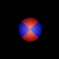
This choice splits trap regions based on whether the orbit point, when trapped, was closer to the real axis or imaginary axis. This is most effective when used with circle or square orbit traps. Effectively, the trap is split into quadrants. For example, this is what the original circle orbit trap looks like when split in this way (we choose blue and red gradients to color the regions.)
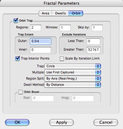
In this next example, create a new fractal window, then bring up the orbit parameter dialog. Check the orbit trap check box, then set the outer trap extent to 0.1 and for Regions Split choose Split by Axis. Then click OK.
Next pick “All Black” from the Palette menu to get a black background. We are going to take one additional step because for this kind of region split, red works better than gray. We are going to change the gray region coloring into red.
Bring up the Color Map Editor window from the Window menu. Choose “Trap[Orbit Real]” from the Regions menu. This should be the region colored gray. Now any palette color you pick will be applied to this region. Go to the Palette menu and choose “Red Gradient.”
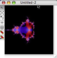
You window should now look like this:
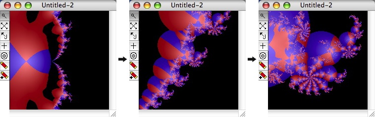
Now let’s zoom into the back portion; we can get something like this:
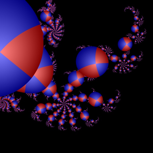
The final image in this sequence looks like this when rendered at 600×600, anti-aliased:
Advanced Tip!
You can change the appearance of images like this by using yet another option in the Orbit parameters dialog, the Multiple menu. Recall that we said earlier that if an orbit is captured by an orbit trap that the first point in the orbit sequence is colored according to the position of the captured point in the orbit trap. But an orbit is a sequence of many points; what if more than one point of the orbit is captured by the trap? In Fractal Domains, one of the multiple points captured will “win” (that is, its position will be used) and the Multiple option determines the rule used to decide. Initially the menu is set to “Use Minimum Captured.” This means that if multiple points are captured, the one that is the minimum distance from the origin will be the one used to determine the color. The other options are “Use First Captured” and “Use Last Captured.” These mean use the first orbit point in the sequence to be captured, or use the last orbit point to be captured.
What does this mean for the appearance of the final image? Each orbit point captured will generally belong to a different “copy” of the orbit trap image in the fractal image, and multiple orbit points occur in places where the images overlap. Choosing “Use Minimum Captured” will result in overlapping images being “merged” as in the figure above.
Generally, when multiple orbit points are captured, the earlier points in the sequence correspond to larger images and the latter points in the sequence correspond to smaller images. So, when “Use First Captured” is chosen, the larger images are shown covering the smaller ones, and when “Use Last Captured” is chosen, the smaller images are shown covering the larger ones.
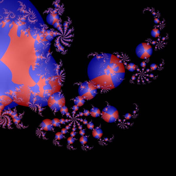
Experience shows that usually much better results (in terms of appearance) can be achieved with “Use First Captured” than with “Use Last Captured,” so let’s change the Multiple choice to “Use First Captured” as follows:
The resulting image (rendered at 600×600 anti-aliased) looks like this: